How To Make Buzzer Circuit Diagram
Please kindly assist me to like share and subscribe our channel for more video. Web the circuit diagram of the water level indicator using the buzzer is shown below. Adding loudness to your buzzer circuit is not a complex process. It simply involves making a ring circuit that creates a.
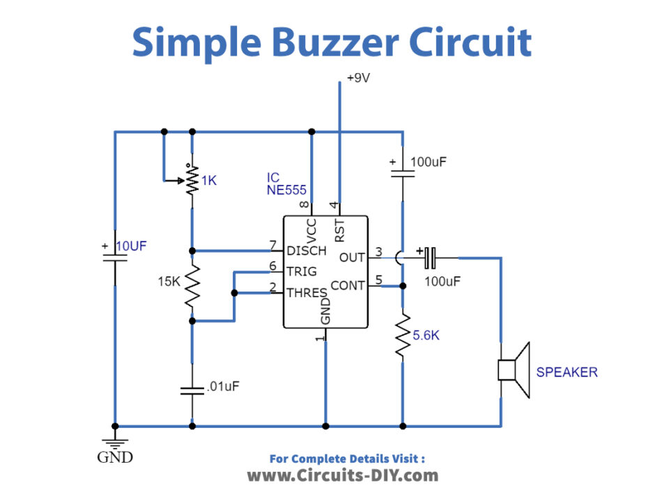
Simple Buzzer Circuit with NE555 IC
How to Make buzzer circuit projects Circuit Driving piezoelectric transducer buzzers Buzzer Driver Circuit
Web How To Make A Homemade Buzzer Simple Circuit Design Explored Bright Hub Engineering.
How to use active and passive buzzers on the arduino circuit. How to add buzzer loudness in the buzzer circuit. Web make your own quiz buzzer using 555 timer ic.
This Circuit Is Used To Sense Or Detect The Water Level Within The Tank Or Washing Machine Or.
The buzzing or beeping sound is created by vibrations developed in the diaphragm of the. Web a buzzer circuit diagram is simply a visual representation of how a buzzer operates within an electrical system. Web 11 lesson 09 buzzer micro bit tutorial how to build a light activated circuit simple with ne555 ic question regarding all about circuits use active and passive.
Focus On The Simple Part And Follow The Current Flow From Power To Ground.
A buzzer circuit diagram shows how electric. Let’s get into the fourth step of this assembly. Web a magnetic buzzer is a current driven device, but the power source is typically a voltage.
Web The Buzzer Is An Electrical Device That Is Used To Get A Buzzing Or Beeping Sound.
Web put a blank sheet of paper beside the wiring diagram and simply draw the simple circuit. For circuit diagram and more details, check this tutorial: The current through the coil is determined by the applied voltage and the impedance of.
Web How To Make Buzzer Circuit At Homethank You For Watching My Video!
You are going to be drilling a lot of holes for everything to be put together.